
Network Analyzer Kits
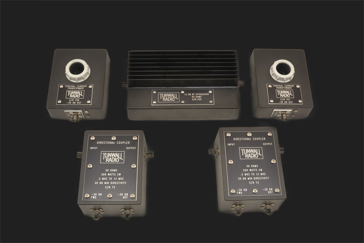
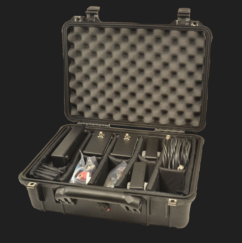
Measure AM antenna systems under power with a Tunwall Radio network analyzer test kit. These devices used with a network analyzer, allow for rapid and accurate swept frequency tests of many electrical parameters. Included in the kit are a pair of directional couplers, a 12dB RF attenuator, and a pair of toroidal current transformers. All are built in cast aluminum enclosures with engraved anodized aluminum labels. Cables, clip leads and low power attenuators complete the set, housed in a pelican case with padded dividers.
The measurement system was developed by the late Ron Rackley, P. E. in papers presented to the NAB. (These are available here). Essentially, a power amplifier on the network analyzer’s output allows test signals to overcome the undesired voltages typically induced on AM towers. The amplified signal (40 to 50dB higher than original) drives the antenna system or other device under test, through the directional coupler. The directional coupler forward and reflected sample voltages are -30dB (assuming a 50 ohm load), and 20dB series pads in front of the network analyzer inputs reduce the voltages further so the samples are within the range of the network analyzer. A power attenuator follows the RF power amplifier to provide some isolation from voltages induced in the towers.
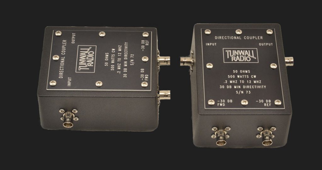
Directional Coupler
The directional coupler uses two ferrite toroid transformers in a balanced circuit to establish voltages corresponding to forward and reflected power. Directivity is at least 45dB over the broadcast frequency range. The circuit provides excellent phase accuracy with minimal insertion effect. The couplers have been tested at 100 watts, and the design power capability is at least 500 watts. The circuit is durable enough for measurements in systems with significant power induced by nearby radio stations without damage.
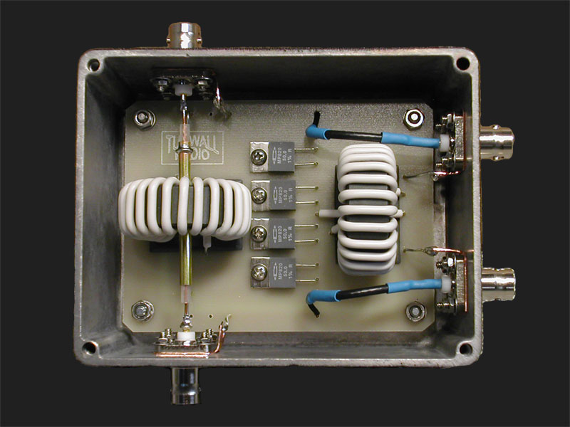
The ferrite toroid rings are mounted in rectangular holes in heavy gauge G-10 (Garolite), with epoxy on both sides. Non-inductive precision resistors are used in the voltage addition/subtraction section of the circuit.
The coupler design has been tested for accurate impedance measurements from 200 KHz to 12 MHz. A print of extensive test data is included with the coupler.
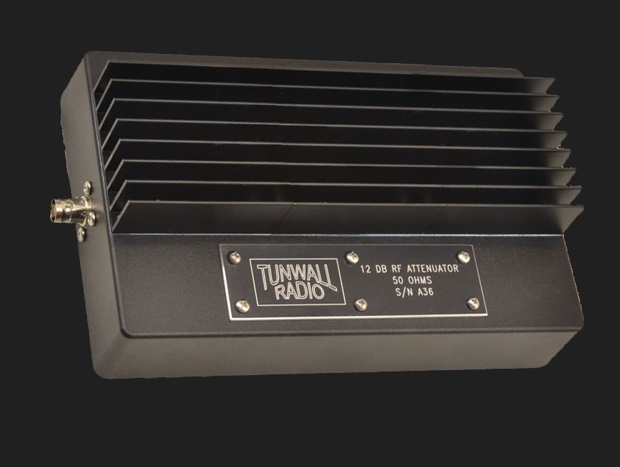
12dB RF Attenuator
The 12dB RF attenuator is designed with 50 ohms input and output impedance, to be connected to an antenna with RF power induced by nearby stations, while passing the output of a power amplifier to the antenna. The attenuator is simple in design, using 9 non-inductive power resistors and a heat sink. Aluminum hardware is used to attach the resistors, cast aluminum enclosure, and heat sink to avoid mechanical stress from thermal expansion. Both ends of the attenuator are identical, so input and output designation is not needed.
The attenuator has been tested up to 100 watts into each end, although this would cause too much heat for continuous operation. Except in the most adverse conditions, power induced in the tower(s) will be less than 100 watts into 50 ohms, and it is not always necessary to operate the power amplifier at 100 watts; some engineers using the power network analyzer system employ amplifiers with 10-25 watts output, which is sufficient for most situations.
A print of extensive test data is included with the attenuator.
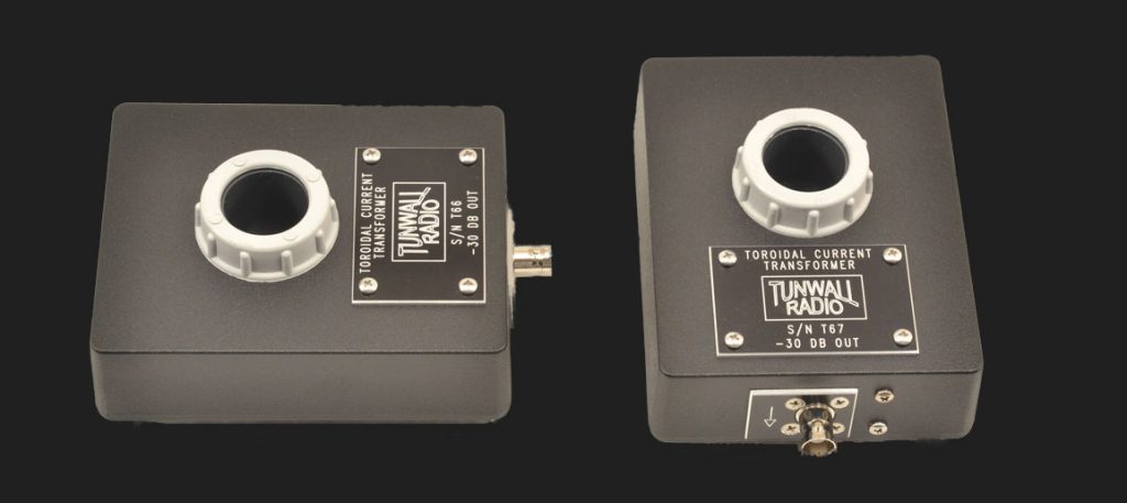
Toroidal Current Transformer
The toroidal current transformer (TCT) is a medium wave current transformer that can be used to measure network response and phase shift characteristics. 32 turns of miniature coax on a ferrite toroid serve as the transformer secondary winding, which is connected to the output jack. An RF conductor through the TCT becomes the one-turn primary winding. A metal enclosure is used to provide complete shielding. A PVC tube runs through the enclosure and toroid, so for drive signals of reasonable voltage, the TCT can hang on copper tubing or small copper strap in phasing cabinets. Any clip lead or other conductor that will fit through the tube may also be used.
The PVC tube is permanently epoxied to one side of the enclosure. The miniature coax is attached to the ferrite ring with several layers of an acrylic compound to make a stable “donut”, which is mechanically secured inside the enclosure but not permanently glued.
The output voltage is 30dB lower than the voltage of the circuit being sampled, assuming a 50 ohm load. An arrow is provided next to the output jack as a phase reference; the TCT can be used “backward”.
The output voltage is constant within 0.5dB from 200 KHz to 2 MHz. From 200 KHz to 5MHz the output is consistent within 2.5dB. A response measurement chart is included with the TCT.
Clip Leads for Directional Coupler
Clip leads for the directional coupler are included. The leads are 12” total length, made from RG-58A/U, with stranded center conductor, for flexibility. The clips are one size smaller than Delta bridge leads, since RF power measured will be watts rather than kilowatts. The leads are also useful for connecting scopes or other equipment to AM networks. Four are included in the kit.
Low Power Attenuators and BNC Cables
Low power 20dB BNC series attenuators are included, as well as BNC cables. 3dB and 6dB BNC attenuators may be convenient values for field work, to quickly reduce output of a fixed-gain power amplifier by attenuating its input (100 watts to 50: 3dB, 100 watts to 25: 6dB).
Network Analyzer Measurement Kit
Contact us for a quote and availability.
| Item | Qty |
| Directional Coupler | 2 |
| Clip Leads for Directional Coupler | 4 |
| Toroidal Current Transformer | 2 |
| 12dB RF Attenuator | 1 |
| Low Power Attenuator BNC Series 20dB | 3 |
| Low Power Attenuator BNC Series 6dB | 1 |
| Low Power Attenuator BNC Series 3dB | 1 |
| BNC Series Cables | 6 |
| Pelican Case with Padded Dividers | 1 |